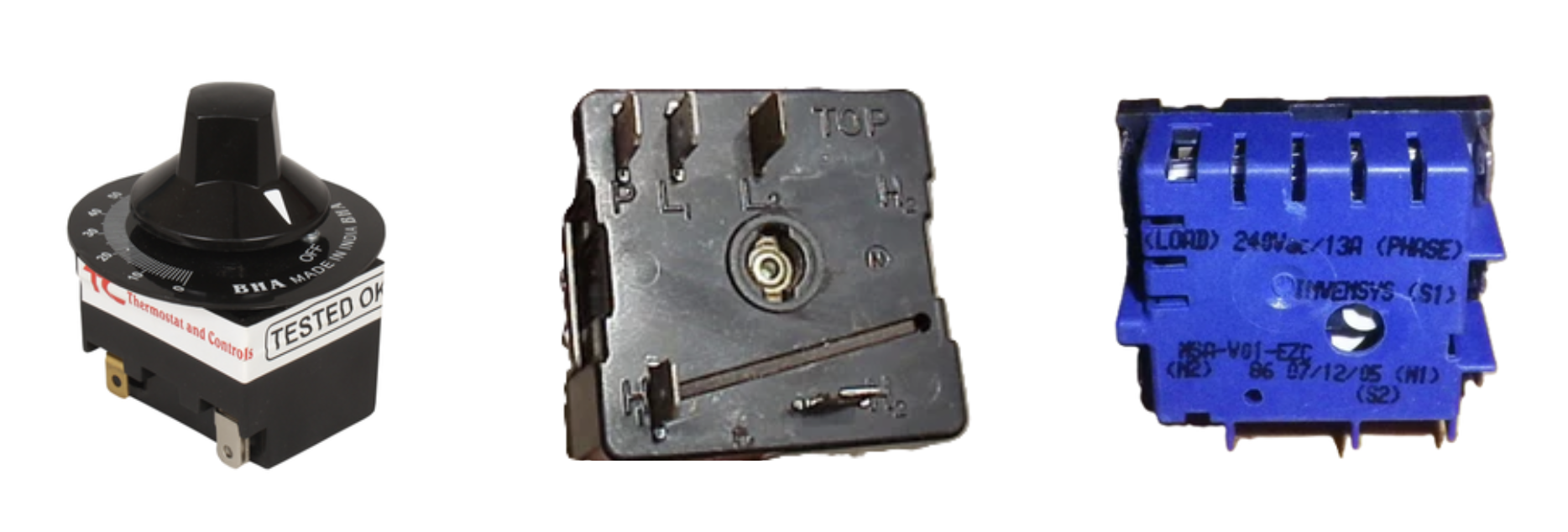
Energy Regulators

An energy regulator, also known as a simmerstat, is a device that controls the amount of electrical power going to a heating element, allowing for precise temperature control. It's commonly used in appliances like stoves, hotplates, and ovens to regulate heat output. The simmerstat achieves this by intermittently switching the power on and off, adjusting the duration of each cycle to control the heat level.
Here's a more detailed look at the functionality and use of an energy regulator/simmerstat:
Function:
- Variable Heat Control: Simmerstats provide a way to fine-tune the heat output of a heating element, allowing for a wide range of temperature settings.
- Intermittent Switching: They work by cycling the power to the heating element on and off, with the "on" and "off" times varying depending on the desired heat level.
- Adjustable Knob: Typically, a knob is used to adjust the ratio of "on" time to "off" time, enabling smooth and continuous heat adjustment.
Applications:
- Stoves and Hotplates: Simmerstats are used to control the heat output of electric stove burners and hotplates.
- Ovens: They can be used to regulate the heat within an oven, ensuring consistent temperature control.
- Other Heating Devices: Simmerstats are also used in other heating applications, such as industrial equipment, where precise temperature control is needed.
Benefits:
- Precise Temperature Control: Simmerstats allow for precise temperature control, which is crucial for many cooking and heating applications.
- Safety: They help to prevent overheating and ensure safe operation of heating devices.
- Energy Efficiency: By controlling the power input, simmerstats can contribute to more efficient heating, reducing energy consumption.
In summary, an energy regulator or simmerstat is a versatile and essential component for controlling heat output in various appliances and industrial applications, offering precise temperature control and contributing to safety and efficiency.
ENERGY REGULATORS (SIMMERSTAT) MODEL TC-201

The Energy Regulators affects its control by periodically switching the power on and off, the ratio of the on time to the total time determining the average power input. As compared with a variable resistance, the energy regulators are in general cheaper, far less bulky and applicable to any load up to its rated capacity. Moreover, the control is affected without the loss of energy associated with resistance control is variable continuously from no load to full load and is substantially independent of mains voltage fluctuations up to about 20%.
Technical Specifications of Energy Regulators
| Line Input | 230V ± 20%, Single phase, 50Hz, 1kW Max, up to 3kW for 3 hours Max. Can supply as per customer’s input specification. |
|---|---|
| Range | 6% TO 85% adjustable |
| Temperature | Can adjust temperature up to 300 Degree Centigrade by dial setting. |
| Isolation | 2.5kV A.C, for 1 minute, leakage current <3.5mA |
| Leakage Current | Less than 210 micro Amp. As per IS 302. |
| Operating Temperature | 0°C – 50°C |
| Life | 1,00,000 Switching cycles under normal conditions. |
| Dimensions | Length - 50mm, Width - 41mm, Height - 74mm approx. |
| Weight | 110gm approx. (Without dial plate) |
| Approvals | Meets VDE, IEC Standards. |
| EMC | CE Marked. |
INFINITE CONTROL SWITCH MODEL TC 202

The infinite control switch / Heat switch gives infinite control / Heat switch for non-inductive loads up to 15 Amps on 120 or 240 V-AC (cannot be used with an external contactor). It can be turned either to left or right to adjust proper heat from 0-100% wattage with infinite control switch over the first 50% of total wattage. Energized continuously in HI position, at other settings it delivers selected input level under control of a simple bimetal timer. Only 3 mounting holes are necessary to install the INFINITE CONTROL / HEAT SWITCH in customer supplied box or panel. It is designed for use at ambient temperatures up to 85°C.
Technical Specifications of Infinite Control Switch / Heat Switch
| Line Input | 230V or 120V ± 20%, 15Amp Max |
|---|---|
| Range | 5% at low – 100% at high, adjustable |
| Isolation | 2.5kV A.C, for 1 minute, leakage current <3.5mA |
| Leakage Current | < 210 µA |
| Operating Temperature | 0°C – 85°C |
| Life | 1,00,000 Switching cycles under normal conditions. |
| Dimensions | Length - 40mm, Width - 40mm, Height - 74mm approx. |
| Weight | 110gm approx. (Without dial plate) |
| Approvals | Meets VDE, IEC Standards. |
| EMC | CE Marked. |
INVENSYS SWITCH MODEL 203

Energy Regulator, Simmerstat Switch series infinite switch with rated voltage 250V, 110V and rated current 16A. It is suitable for electric ovens, electric cookers, sausage grilling machines and plastic machinery.
Energy Regulators control temperature by switching the current on or off for shorter or longer intervals. At the highest level, power is continuously supplied. The energy regulators are installed directly behind the control knob. When switched on, a bimetallic strip heats up, changes its shape, and triggers the corresponding contacts. The control knob position determines the distance between the bimetal strip and the controller contact, which allows the current to flow at a correspondingly high rate.
Basic Info
| Model NO. | NT-R78 |
|---|---|
| Product Type | Burner Switch |
| Voltage | 110V-250V |
| Material | Plastic |
| Power Source | Electric |
| Application | Home Application |
| Colour | Blue/White/Black |
| Transport Package | Carton |
| Trademark | RULE |
| HS Code | 90321000 |
