
Accessories
SNAP DISC THERMOSTAT
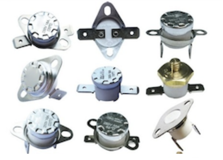
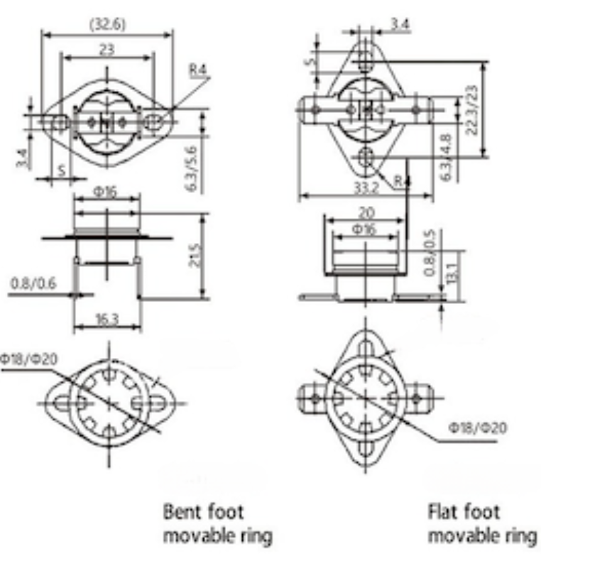
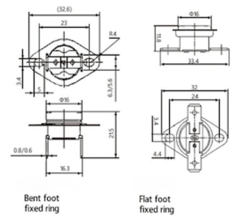
The KSD301 snap action thermostat series operates based on the rapid movement of the disc-shaped bimetal when exposed to temperature changes. With the mechanism's push rod in motion, its contacts swiftly move to establish disconnection and connection as needed.
TECHNICAL PARAMETERS:
- Contact type:NC/NO
- Body material: Bakelite / Ceramic
- Ring type:Fixed Ring/Movable Ring/No Ring
- Reset model:Auto Reset/Manual Rest/No Reset
- Terminal size:6.4*0.8/4.8*0.8/4.8*0.5mm
- Temperature range: 30°C~250°C
- Electrical strength: AC1800V/min without breakdown and flashover
- Action life: ≥ 100,000 times
- Rated current:DC24V-10A, AC250V-10A/16A
APPLICATIONS:
Water dispenser, electric water bottle, coffee stove, drip coffee machine, water heater, microwave oven, electric oven, electric baking pan, electric frying pan, electric rice cooker, sandwich oven, soybean milk machine, dishwashers, and vacuum cleaners are some household appliances listed.
THERMAL PROTECTOR
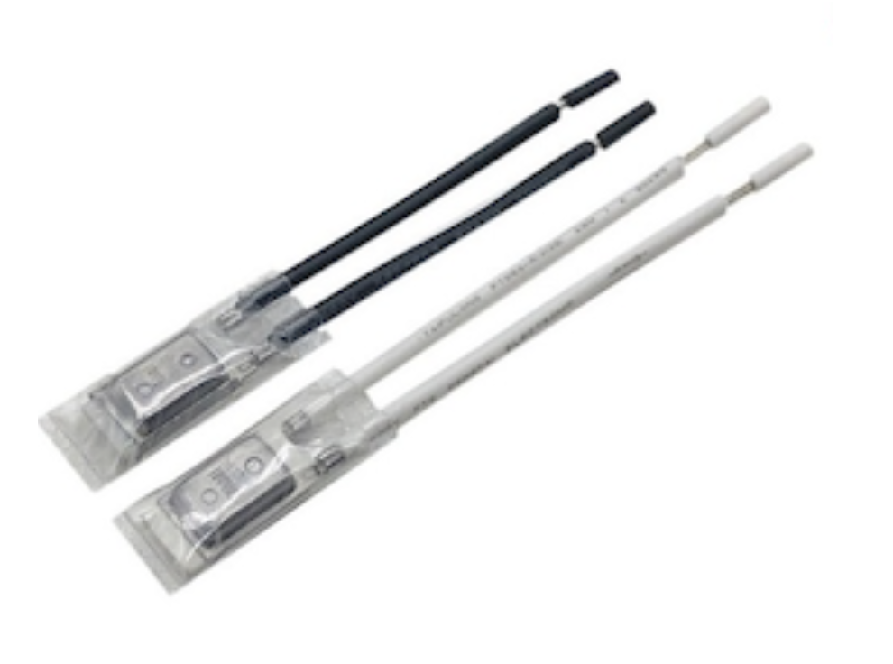
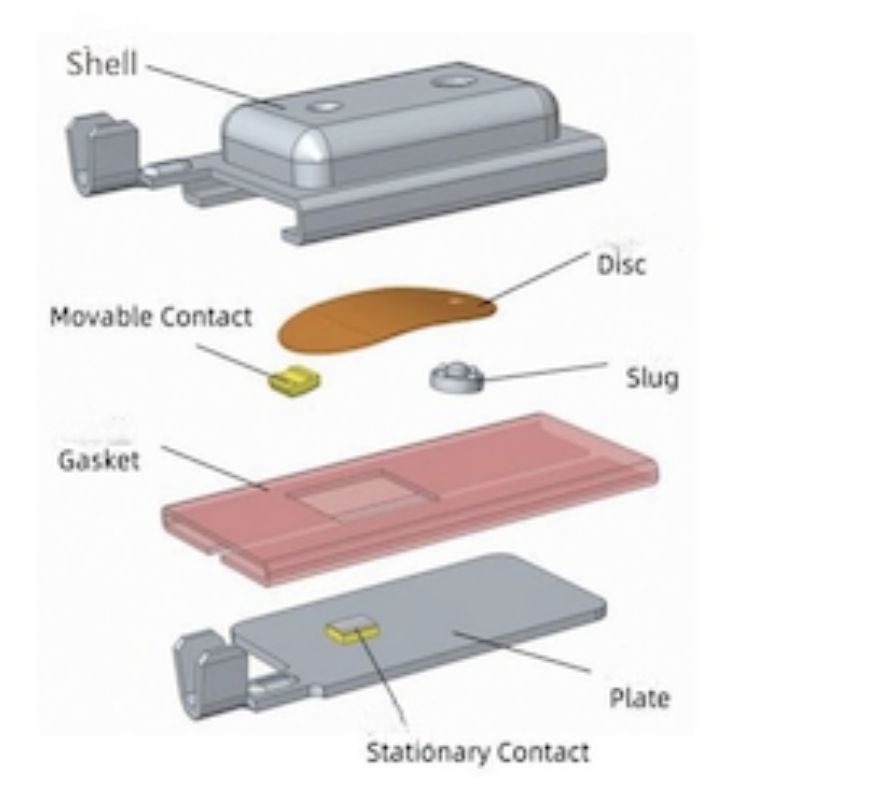
Thermal Protectors made up of Shell, Slug, Disc, Gasket, Plate and Contact(Wire and sleeve can be added according to customer' s requirement). It is a dual protection device for over temperature and over current
PRODUCT FEATURES:
The thermal protector has the characteristics of small size, high current, sensitive operation, and long service life
TECHNICAL PARAMETERS:
- Contact type: NC
- Temperature range: 55°C~180°C
- Temperature tolerance: + 5 °C
- Contact resistance: ≤ 50m 2
- Electrical strength: AC2500V/min without breakdown and flashover
- Action life: ≥ 100,000 times
- Rated current:DC16V-20A, AC115V-22A,AC250V-9A
APPLICATION RANGE:
Motor and pump, Battery packs, Vacuum cleaner, Heating appliance
3 PHASE SSR DC TO AC | AC TO AC
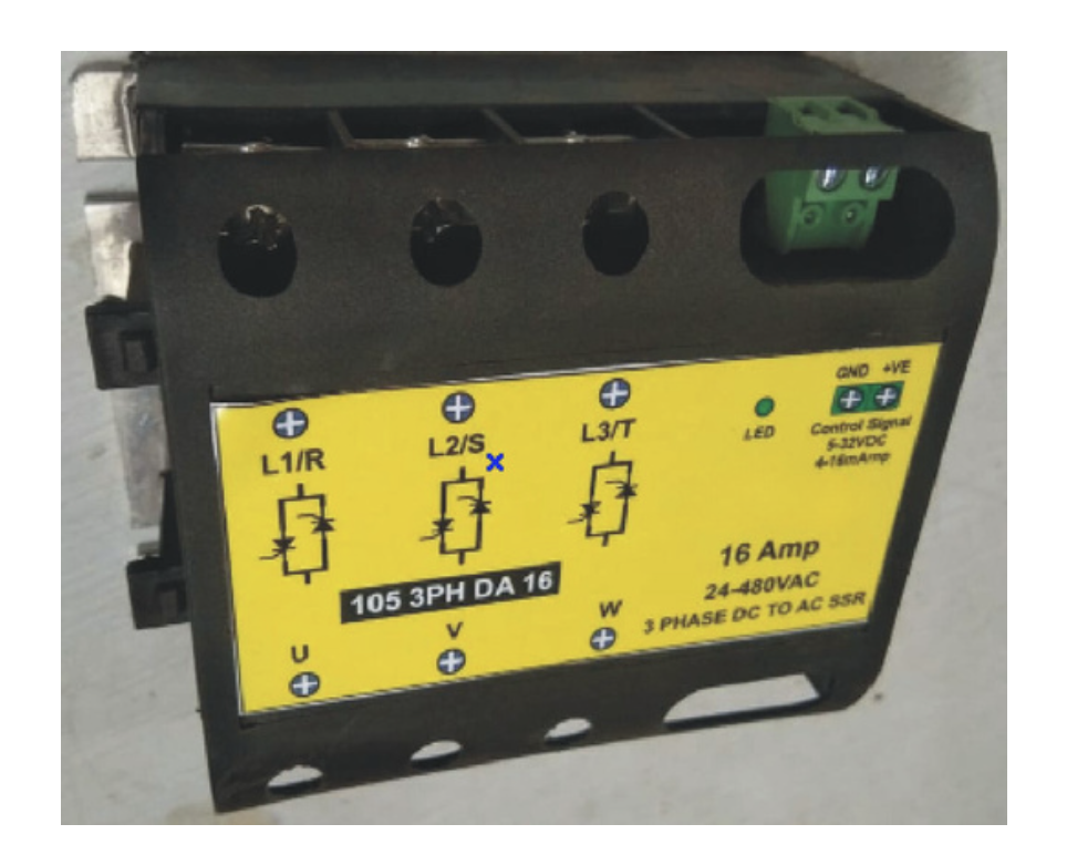
Three phase "Zero Crossing"solid state relay is designed for control of resistive and inductive loads. Three phase state relay is available in AC or DC Control Signal with LED Indication. The series RI4P cover a range of load currents up to 16A to 90A Acrms.
PRODUCT FEATURES:
- DC or AC control signal input
- LED indication for input control
- Reverse polarity protection
- Additional Functionalities
- Zero crossover switching
- Inbuilt snubber
- Compact size
- Installation and Protection
- Din rail mounting
- Inbuilt transient voltage suppressor
- Minimal EMI/RFI interference
Technical Specifications
| Parameters | Unit | Back to Back SCR |
|---|---|---|
| Operating Voltage Range (Vrms) | Vrms | 24–480 VAC |
| Peak Inverse Voltage | Vpk | 1200Vpk |
| Frequency Range | Hz | 45–65 Hz |
| Max. Off-state Leakage Current | mA | ≤2 mA |
| Operating Load Current | Itrms | 16A, 25A, 50A, 90A |
| Minimum Load Current | IH | 60mA, 175mA, 275mA |
| Maximum Surge Current (t=10mSec) | ITSM | 160A, 340A, 775A, 1200A |
| Maximum On-State Voltage Drop | VTM | 1.5V, 1.35V |
| Maximum I²T for Fusing | I²T | 128A²S, 500A²S, 30000A²S, 72000A²S |
| 3 Phase Motor | HP / KW | 1HP / 0.75KW, 3HP / 2.25KW, 7.5HP / 5.5KW, 10HP / 7.5KW |
| Minimum Off-State dv/dt | dv/dt | 200V/µs, 500V/µs, 1000V/µs |
| Critical di/dt @ 50 Hz | di/dt | ≥50A/µs, ≥100A/µs |
| Thermal Resistance Junction to Case | Rjc (°C/W) | 3.9, 1.1, 1, 0.4 |
| Power Factor | Cosφ | ≥0.5 (at 600VAC) |
General Specification
| Parameters | Unit | Value |
|---|---|---|
| Input to Output Isolation Voltage | Vrms | 4KVrms |
| Input, Output to Body Isolation Voltage | Vrms | 4KVrms |
| Ambient Operating Temperature Range | °C | -30°C to +80°C |
| Weight | gms | 88gms |
| Dimensions | mm | 100 x 73.5 x 43 (L x W x H) |
Note 1: All parameters specified at 25°C unless otherwise specified.
Note 2: When mounted to proper size heat sink (see derating curves)
Three Phase Load Calculation
Delta Connected Load:
P = 1.73 × VL × IL × cosφ
P = 3 × VL × IL × cosφ
For resistive loads, cosφ = 1.0
Wye Connected Load:
P = 1.73 × VL × IL × cosφ
P = 3 × VP × IL × cosφ
For resistive loads, cosφ = 1.0
Quick Formula
Where P = total 3-phase power in kW:
For VL = 480V → IL = 1.2 × P (in kW)
For VL = 240V → IL = 2.4 × P (in kW)
For VL = 208V → IL = 2.8 × P (in kW)
SINGLE PHASE SSR DC TO AC | AC TO AC
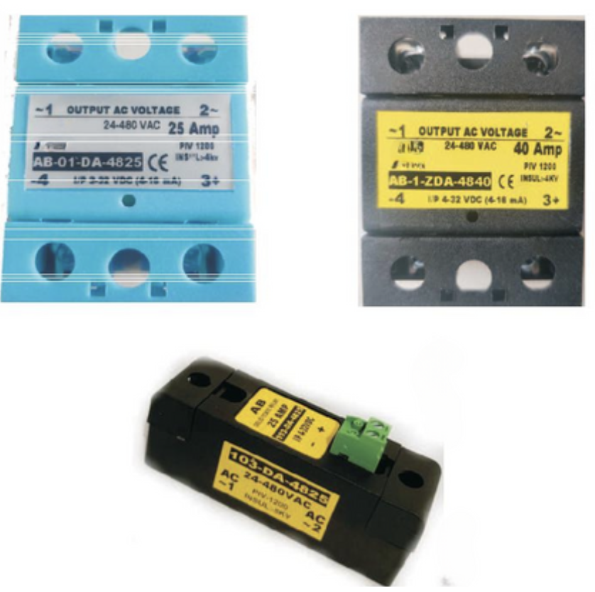
Three phase "Zero Crossing"solid state relay is designed for control of resistive and inductive loads. Three phase state relay is available in AC or DC Control Signal with LED Indication. The series RI4P cover a range of load currents up to 16A to 90A Acrms.
PRODUCT FEATURES:
- Input Control Features
- AC or DC control
- LED indication for input control
- Reverse polarity protection
- Switching and Protection
- Zero crossover switching
- Built-in snubber
- Transient voltage suppressor
- Design and Performance
- Compact size
- Minimal EMI/RFI interference
- DIN rail mounting
- Noiseless, fast switching without chattering
Technical Specifications
| Parameters | Unit | DC Input | AC Input |
|---|---|---|---|
| Control Voltage Range | VDC | 4–32 VDC | 80–280 VAC |
| Control Current Range | mA | 4–16 mA | 4–16 mA |
| Parameters | Unit | TRIAC or SCR |
|---|---|---|
| Operating Voltage Range (Vrms) | Vrms | 24–330 VAC / 24–480 VAC / 24–600 VAC |
| Peak Inverse Voltage | Vpk | 800Vpk / 1200Vpk |
| Rated Operational Current | AC 51–20°C | IT | 16A AC, 25A AC, 40A AC, 50A AC, 90A AC |
| For Utilization Category | AC 53a–55°C | IT | 8A AC, 12A AC, 20A AC, 28A AC, 35A AC |
| Minimum Holding Current | IH | 50mA, 75mA, 60mA, 275mA |
| Rated Peak Withstand Current (t=10 ms) | ITSM | 160A, 250A, 400A, 775A, 1200A |
| Max. Load Integral I²t (t=10 ms) | I²T | 144A²S, 340A²S, 880A²S, 3000A²S, 7200A²S |
| Voltage Drop in On-State | VTM | 1.3V |
| Critical Current Gradient | di/dt | ≥50A/µs, ≥100A/µs, ≥150A/µs |
| Critical Voltage Gradient | dv/dt | 500V/µs, 1000V/µs, 1500V/µs |
| Thermal Resistance Rth (Junction to case) DC | ϕ j-c | 1.1, 2, 0.9, 1, 0.4 |
| Frequency Range | Hz | 45–65 Hz |
| Max. Off-State Leakage Current | mA | ≤2 mA |
| Maximum Barrier-Layer Temperature | °C | 125°C |
| Power Factor | Cosφ | ≥0.5 (at 600VAC) |
| Electrical Wire Size (Max.) | O/P / I/P | 16 Sqmm Lugs / 4 Sqmm Lugs |
| Input to Output Isolation Voltage | Vrms | 4KVrms |
| Input, Output to Body Isolation Voltage | Vrms | 4KVrms |
| Ambient Operating Temperature Range | °C | -30°C to +80°C |
| Weight | gms | 88gms |
| Dimensions | mm | 58 x 45 x 32 (L x W x H) |
Note 1: All parameters specified at 25°C unless otherwise specified.
Note 2: When mounted to proper size heat sink (see derating curves)
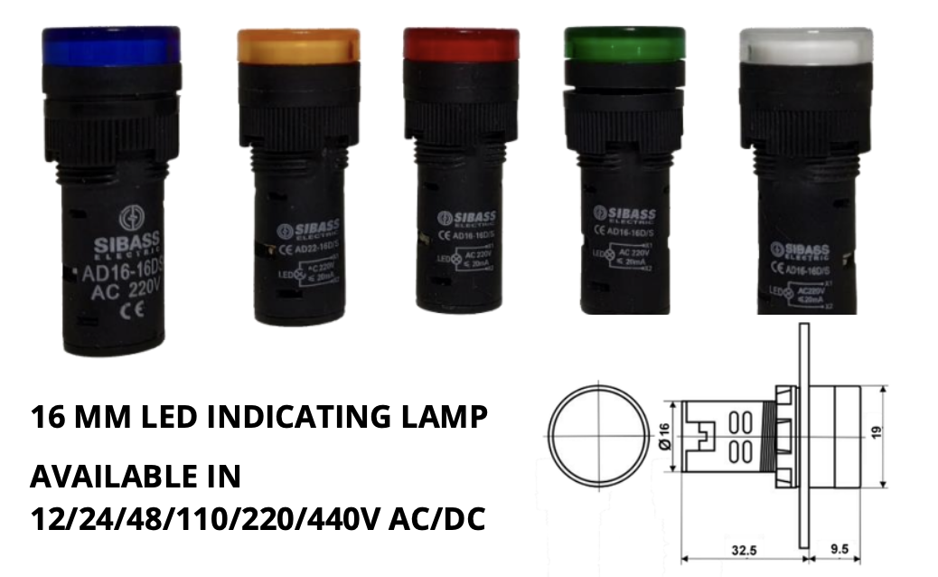
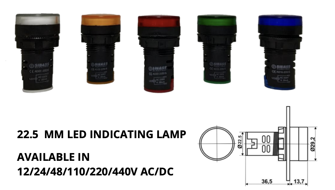
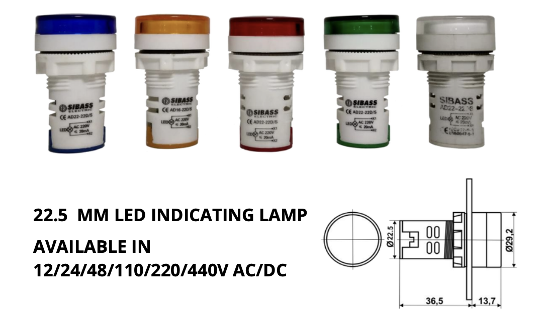
LED INDICATING LAMP - BLACK BODY
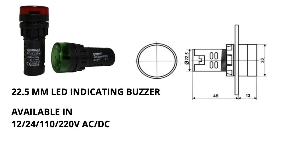
LED INDICATING LAMP WITH BUZZER
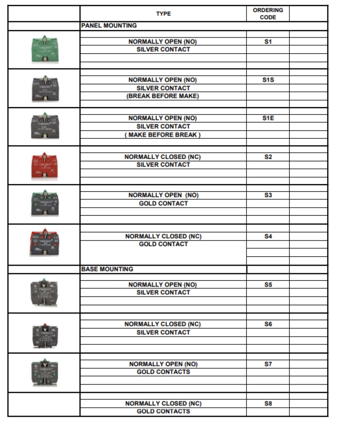
NO/NC ELEMENTS
PUSH BUTTONS
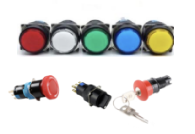
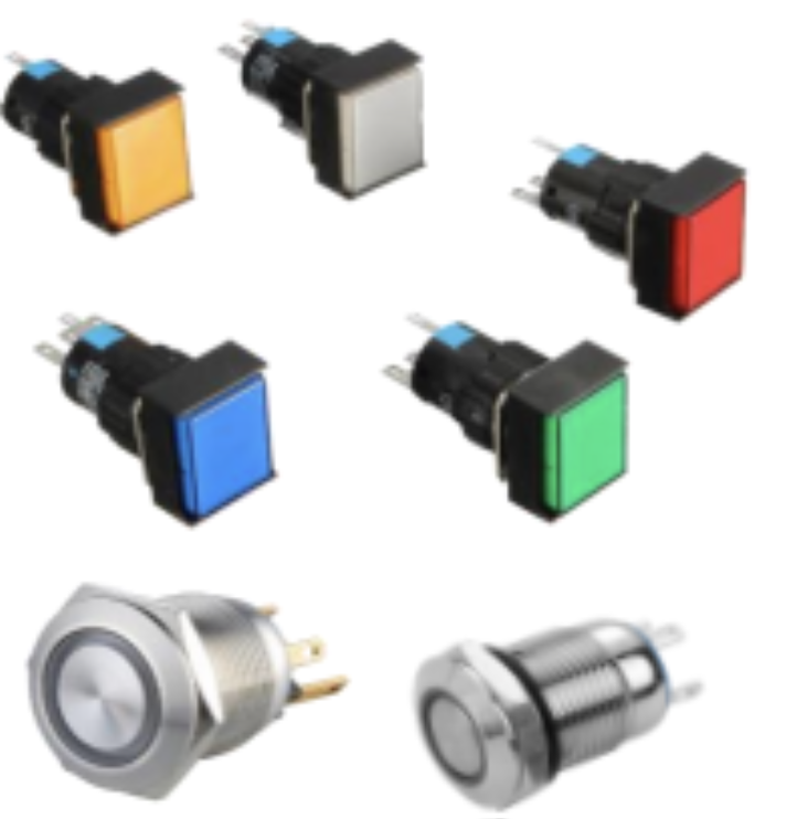
PUSH BUTTONS SWITCHES
The push button switch is usually used to turn on and off the control circuit, and it is a kind of control switch appliance that is widely used. It is used in electrical automatic control circuits to manually send control signals to control contactors, relays, electromagnetic starters, etc
SS PUSH BUTTON WITH LED:
- Install diameter:12/16mm
- Switch rating: 10A/250VAC
- Shape: Flat head
- Terminal: Pin terminal
- Crust material: stainless steel
- IP rating: IP65 / IP67 can be customized
- Temperature: - 40 to 75 Degree
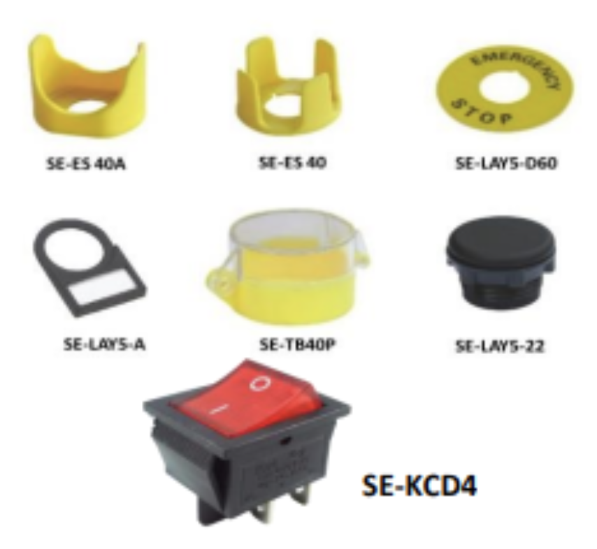
EMERGENCY STOP SWITCHES
Emergency stop buttons are wired in series with the control circuit of machinery equipment. When pushing the mushroom head of emergenty stop button will break the circuit of machinery equipment and removes power supply from the that keeps the circuit energized
ROCKER SWITCH
Rocker switches are electromechanical devices that control the start or stop function in circuits. They use an actuator that rocks along the center axis. These switches, commonly found in power supply boards and electronic equipment, ensure reliable long-term functionality.